Installation Procedure for Water Level Controller:
Basic Model Level Controller for (220V AC) Single Phase Pumpset Starter.
Installation of our water level controller system is not a major task and we have made the system in such a way that it is possible to install the system yourself with minimum electrical knowledge or with the help of a simple electrician. The task of installation comprises of two parts, the Power Connection and the Sensing Connection.
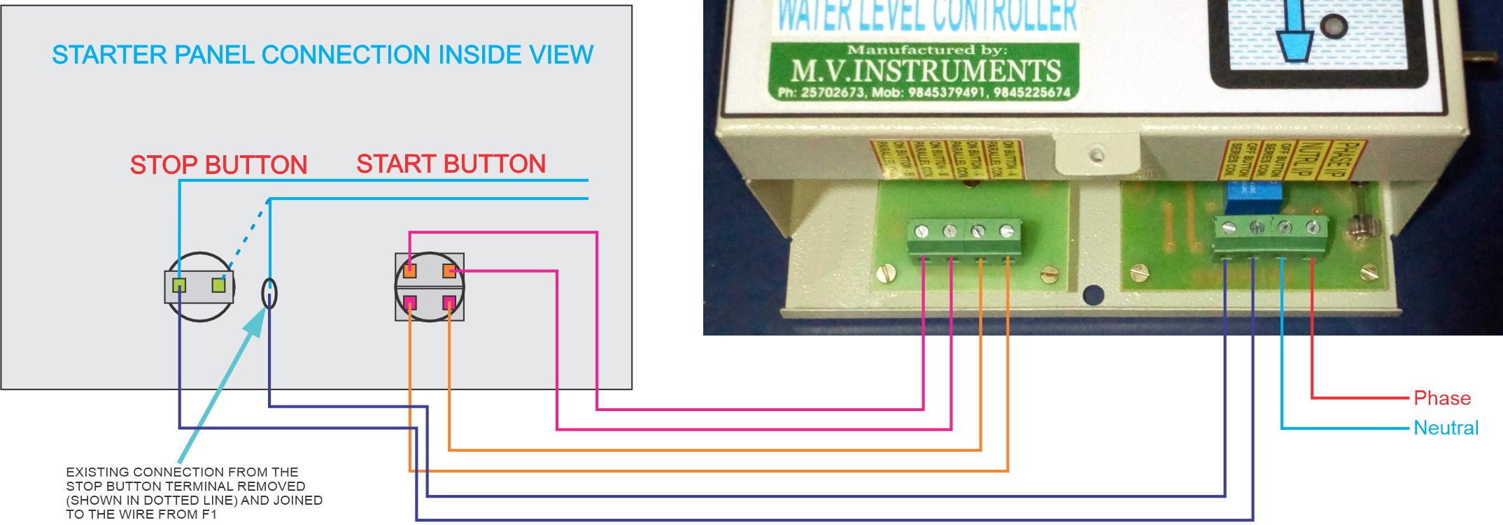
The Power Connection is the connection between the Water Level Controller and your existing Starter with which you are presently operating the Pumpset. The Single Phase Borewells will usually have a starter with start capacitors and run capacitors inside. The starter will have voltage and current meters with ON and OFF Push Buttons on the Door of the Panel. To Control such starters the control wiring will be done only to the ON and OFF Push Buttons. Sensing Connection includes the cabling of sensing wire, i.e., 4 pair CAT 5e Communication Cable from the Water Level Controller to the Overhead Tank (OH Tank). After cabling, making the level sensing arrangement in the water tanks and Sensing connection of the sensing cable to the Water Level Controller.
Tools required for Installation:
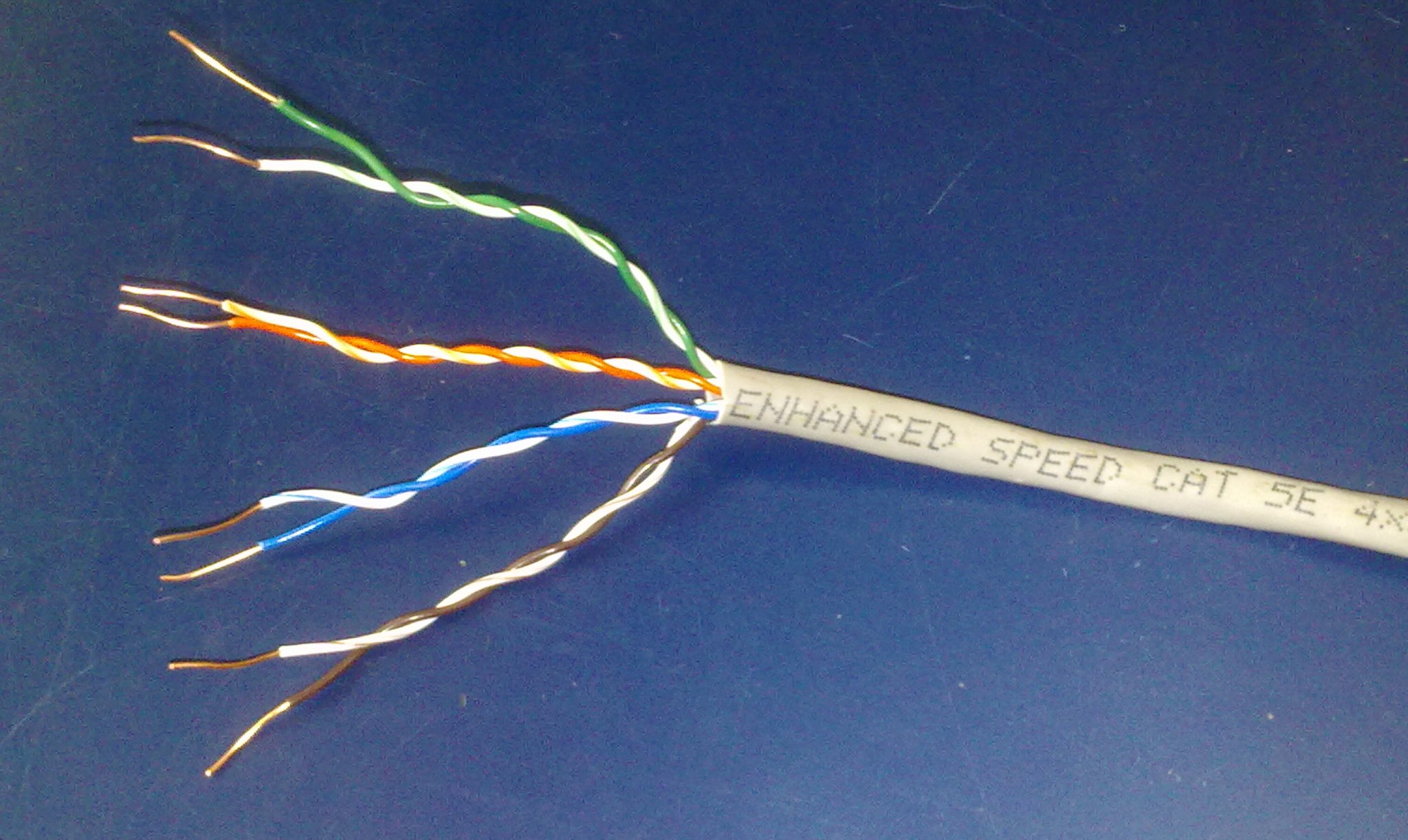
- 4 Pair CAT 5e Communication cable as per requirement. Take a rough estimate of cable length from the pump control switch location to the OH Tank and again from the pump control switch to the UG Sump (for Bore well, cable is required only for the OH tank).
- One length of 3/4th or 1 inch dia. PVC Electrical Pipe for sensor arrangement in the tanks.
- Multi strand 1.5 Sq.mm. Copper Power cable of about 2 to 6 meters as per requirement.
- Line Tester.
- Insulation Tape, necessary screws and wooden gattas pieces for mounting controller unit on the wall.
- Cutting Pliers or Nose Pliers.
- Simple Hammer-Jumper set or Drill Gun to mount the Level Controller to wall or to wooden board.
Single Phase Pumpset pumping from Borewell to Overhead Tank or Underground Sump.

Sensing Cable Connection to Water Level Controller.
STEP 1. Remove the bottom cap of the Water Level Controller and identify the coloured sensing wire bunches on the bottom opening of the Unit.
STEP 2. The sensing wires comprises of two bunches of wires, one bunch of three wires(and a pair of thin wire) for sump or lower tank and another bunch of four wires for upper tank.
STEP 3. Do complete sensing wiring from Water Level Controller to Overhead Tank and Water Level Controller to Underground Sump / Well.
STEP 4. To connect the sensing wires of Tank and Sump / Well, to the Water Level Controller unit, simply twist the wires to the respective wires of Water Level Controller unit in the following manner. Slide the black PVC sleeve provided over the twisted joint completely. The advantage of having loose sensing wire over the sensing terminal block is that, loose contacts are avoided and testing of the controller functions can be done easily by shorting the sensing wires of controller directly.
STEP 5. OH Tank Sensing Connection with bunch of Five wires: -
| Description | Colour of Wire in Sensing Cable | Colour of Wire in Controller |
| PUMP OFF. | Orange | Red. |
| PUMP ON. | Green | Green |
| SIGNAL COMMON. | Blue | Black |
| SIGNAL GROUND | Do not Connect | Blue |
| White wires will not be connected anywhere. Insulate and leave them inside the Level Controller. | ||
STEP 6. As the source of water is Borewell, the sump sensing function have to be bypassed in the controller itself. To bypass the sump sensing function, Black wire, Green wire and Red wire have to be just shorted and insulated with Insulation tape.
| Description | Colour of Wire in Sensing Cable | Colour of Wire in Controller |
| PUMP ON. | Orange | Red. |
| PUMP OFF | Green | Green |
| SIGNAL COMMON. | Blue | Black |
| White wires will not be connected anywhere. Insulate and leave them inside the Level Controller. | ||
| Delay Wire | Keep these wires open when installation and testing are done. After the testing is done successfully,short these two wires permanently. This will enable 15 Sec. ON delay to the controller every time when starting the Pump. | |
| Delay Wire | ||
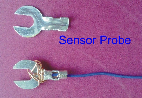
Sensor Probes Connections and Sensors Level setting in Overhead Tank.

Overhead Tank Sensing Procedure:
STEP 1. Do the 4 pair CAT 5e sensing wire cabling from the level controller to overhead tank and leave 1.5 to 2 meter extra cable near overhead tank.
STEP 2. To give the Sensing connection in the Overhead Tank, initially decide the levels at which the pump has to switch ON and switch OFF. As usual procedure, ON Level can be 50% of tank capacity and OFF Level can be 2 to 3 inches less than 100% capacity of Tank (Overflow Level).
STEP 3. Take an electrical PVC pipe of 3/4th inch or 1 inch which is commonly available. Cut the pipe about 2 inch less than the height of the tank so that pipe can be hanged vertically inside the tank.
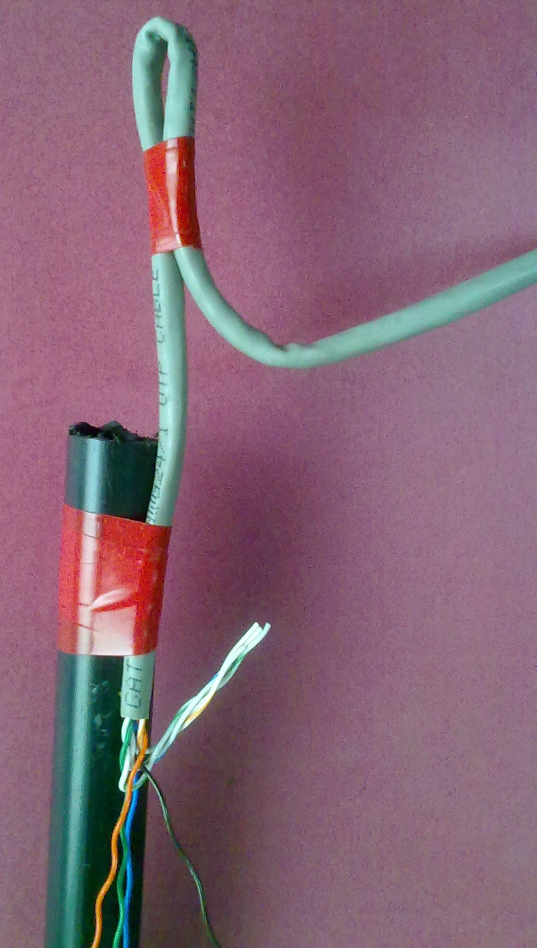
STEP 4. Sleeve the outer grey sleeve of the sensing wire upto the height of the PVC pipe. Fix the grey portion of the wire to the top of the PVC pipe with insulation tape as shown in the Photo with the regular insulation tape.
STEP 5. Make the loop of the sensing wire, as shown in the Photo to hang the sensing arrangement to the top portion of the tank with the help of a hook or nail.
STEP 6. The sensing arrangement should be away from the wall of the tank and also should be away from the water falling into the tank.
STEP 7. Separate the white wires from the coloured wires and cut the white wires and brown wire and isolate it above the Pump OFF Sensor as shown in the Photo. These wires are not used and will remain as extra for any future requirement.
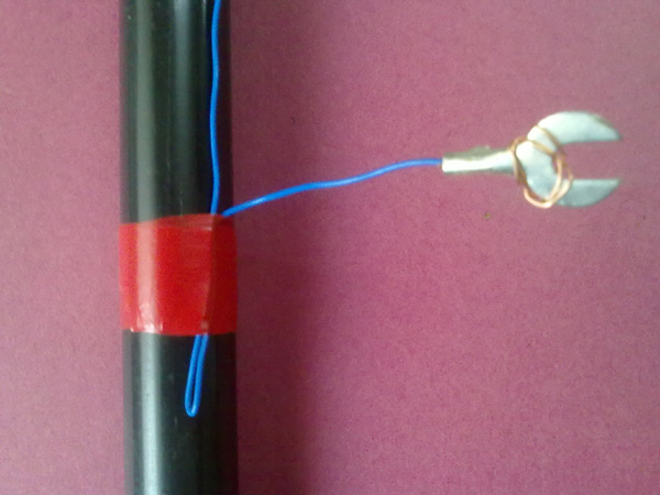
STEP 8. Sleeve Orange, Green and Blue wires for about 3 to 4 inch, twist the sleeved wire around the sensors provided and crimp the sensors to the end of those wires as shown in the Photo. Now fix the sensors at different levels of the pipe as per the levels decided, with insulation tape as shown in the Photo in the following order: -
- Set the level of Common sensor (Blue wire) at the bottom of the Tank.
- Set the level of Pump ON sensor (Green wire) at the Half level of the Tank.
- Set the level of Pump OFF sensor (Orange wire) at the Full level of the Tank.
Underground Sump Sensing Procedure.(Not applicable for Borewell Pumpsets.)

STEP 1. Do the 4 pair CAT 5e sensing wire cabling from the level controller to underground sump and leave 1.5 to 2 meter extra cable near underground sump.
STEP 2. To give the Sensing connection in the underground sump, initially decide the levels at which the pump has to switch ON and switch OFF. As usual procedure, ON Level can be 30% of tank capacity and OFF Level can be 4 to 5 inches above the Foot valve of the suction pipe of Pumpset.
STEP 3. Take an electrical PVC pipe of 3/4th inch or 1 inch which is commonly available. Cut the pipe about 12 inches less than the height of the sump so that pipe can be hanged vertically inside the sump.
STEP 4. Sleeve the outer grey sleeve of the sensing wire upto the height of the PVC pipe. Fix the grey portion of the wire to the top of the PVC pipe with insulation tape as shown in the Photo with the regular insulation tape.
STEP 5. Make the loop of the sensing wire, as shown in the Photo to hang the sensing arrangement to the top portion of the sump with the help of a hook or nail.
STEP 6. Separate the white wires from the coloured wires and cut the white wires and brown wire and isolate it above the Sump high Sensor as shown in the Photo. These wires are not used and will remain as extra for any future requirement.
STEP 7. Sleeve Orange, Green and Blue wires for about 3 to 4 inch, twist the sleeved wire around the sensors provided and crimp the sensors to the end of those wires as shown in the Photo. Now fix the sensors at different levels of the pipe as per the levels decided, with insulation tape as shown in the Photo in the following order: -
- Set the level of Common sensor (Blue wire) at the bottom of the Sump.
- Set the level of Pump OFF sensor (Green wire) at the bottom of the Sump at about 4 to 5 inches above Foot Valve level in the Sump.
- Set the level of Pump ON sensor (Orange wire) approximately at One Foot above the Sump medium sensor in the Sump.
Important: The Sensing wire from the unit to OH Tank and unit to UG Sump / Well should be a one-piece wire and there should be absolutely no joints in these Sensing wires and these wires should not be damaged in any way. Unit will not operate correctly in these cases. Continuity of wire should be checked before wire is laid. This sensing wire can be put inside PVC pipe throughout for extra protection.
